Light Alkane Dehydrogenation to Light Olefin Technologies a Comprehensive Review
![]()
Modification by SiOtwo of Alumina Support for Light Alkane Dehydrogenation Catalysts
A. Butlerov Institute of Chemistry, Kazan Federal University, Kazan 420008, Russia
*
Author to whom correspondence should be addressed.
Bookish Editor: Keith Hohn
Received: two September 2016 / Revised: 11 October 2016 / Accepted: thirteen October 2016 / Published: 20 Oct 2016
Abstract
Due to the continuously rise demand for C3–Cv olefins information technology is important to amend the performance of catalysts for dehydrogenation of calorie-free alkanes. In this work the event of modification by SiO2 on the properties of the alumina support and the chromia-alumina catalyst was studied. SiO2 was introduced by impregnation of the support with a silica sol. To characterize the supports and the catalysts the post-obit techniques were used: low-temperature nitrogen adsorption; IR-spectroscopy; magic bending spinning 29Si nuclear magnetic resonance; temperature programmed desorption and reduction; UV-Vis-, Raman- and electron paramagnetic resonance (EPR)-spectroscopy. It was shown that the modifier in amounts of 2.5–seven.5 wt % distributed on the support surface in the form of SiO ten -islands diminishes the interaction between the alumina support and the chromate ions (precursor of the active component). As a result, polychromates are the compounds predominantly stabilized on the surface of the modified support; under thermal activation of the catalyst and are reduced to the amorphous Cr2O3. This in turn leads to an increase in the activity of the catalyst in the dehydrogenation of isobutane.
one. Introduction
Catalysts with surface chromium species as an active component have large practical importance and are widely used in industrial organic synthesis. Microspherical chromia-alumina catalysts for paraffin dehydrogenation in terms of consumption hold the leading position in the petrochemical manufacture of Russian federation [1]. This process is intended for production of C3–C5-olefin which is the raw fabric for synthesis of rubbers, plastics, synthetic films and filaments, loftier-octane components of fuel, etc. [2].
There are 2 methods of microspherical chromia-alumina catalysts preparation: the mixing of precursors of the support and agile component followed past spray drying of the slurry obtained [3]; and the impregnation of the back up by the solutions of the active component and the promoter. The catalysts obtained by the commencement method accept a low mechanical strength under the conditions of a fluidized bed and the continuous apportionment betwixt the reactor and regenerator [4]. The method of support impregnation seems the most promising. Before a method of a gibbsite transformation to boehmite (precursor of γ-Al2Oiii) in the book of the microgranule by a sequential thermal and hydrothermal treatment was adult [five]. The back up obtained that way has a loftier mechanical strength, middle porosity, and a depression surface acerbity.
Continuously rising need for light olefins [2,6] likewise equally the increase in the cost of natural energy resource requires high active and selective catalysts. It is possible to ameliorate the catalyst performance by introduction of the modifiers. The modifiers of chromia dehydrogenation catalyst SiOtwo [7], ZrO2 [8,9,ten], lanthanum [ten,11], tin [vii,12] and cerium [13] are usually used. Among these modifiers SiOii is the near attainable and inexpensive; its use is broadly described in the patent literature [14]. However, the mechanism of its positive effect on the functioning of the dehydrogenation goad has not been described in detail. Therefore, in this article nosotros studied the effect of modification of the structure and properties of the novel alumina support and chromia-alumina catalyst by SiO2.
2. Results and Discussion
ii.1. Alumina Back up
2.1.ane. Thermal Treatment of Boehmite Precursor
The microspherical back up was used equally a precursor of alumina (Figure 1). It was obtained according to the Scheme one [5]:
Co-ordinate to the 10-ray diffraction (Effigy 2), the alumina forerunner is a well-crystallized boehmite with crystallite size D (020) = 44 nm and D (120) = 47 nm. A loftier degree of boehmite crystallinity causes its small specific surface expanse (Southward BET) and pore volume (5 p) = 27 k2·thousand−one and 0.07 cmiii·chiliad−ane respectively (Tabular array i).
The selection of the boehmite thermal treatment temperature was made based on changes in the specific surface area and the number of strong acid sites (with the energy of ammonia desorption E des.NH3 more than 150 kJ·mol−1) obtained in alumina (Table 1). Information technology is known that potent acid sites are active in hydrocarbon cracking reactions [fifteen,16].
Thermal treatment of the precursor at 750 °C leads to the germination of mesopores (Figure iii), an increase in the specific surface surface area upwards to 92 mtwo·thousand−1 and in the pore volume upward to 0.27 cm3·g−1 every bit a result of dehydration and the phase transition of boehmite to γ-AliiOiii (Figure 2). An increase of treatment temperature to 850 °C resulted in the decrease of the specific area to 62 gtwo·g−1 due to pore enlargement (Table 1).
It is also accompanied past a decrease in the number of strong acid sites due to the reduction of the support surface, its dehydroxylation, as well as the transformation of the crystal structure of the support.
Nosotros believe the optimal temperature of boehmite precursor treatment is 800 °C. γ-AltwoO3 support obtained under those atmospheric condition has a low concentration of stiff acid sites (x.0 μmol·thousand−one) and a medium surface area (Due south BET = 83 mii·g−one). A decrease of the temperature to 750 °C is accompanied past a one.half-dozen-fold increase in the concentration of strong acrid sites (upwardly to 16.2 μmol·g−1) and an increase of surface surface area by merely ix k2·thou−1 (upwardly to 92 m2·one thousand−1). An increase of the temperature to 850 °C leads to a decrease in the specific surface expanse past 21 one thousand2·yard−ane and a decrease in the concentration of stiff acrid sites by but 1.five μmol·g−i (Tabular array one).
two.1.2. SiOii-Modification of the Support
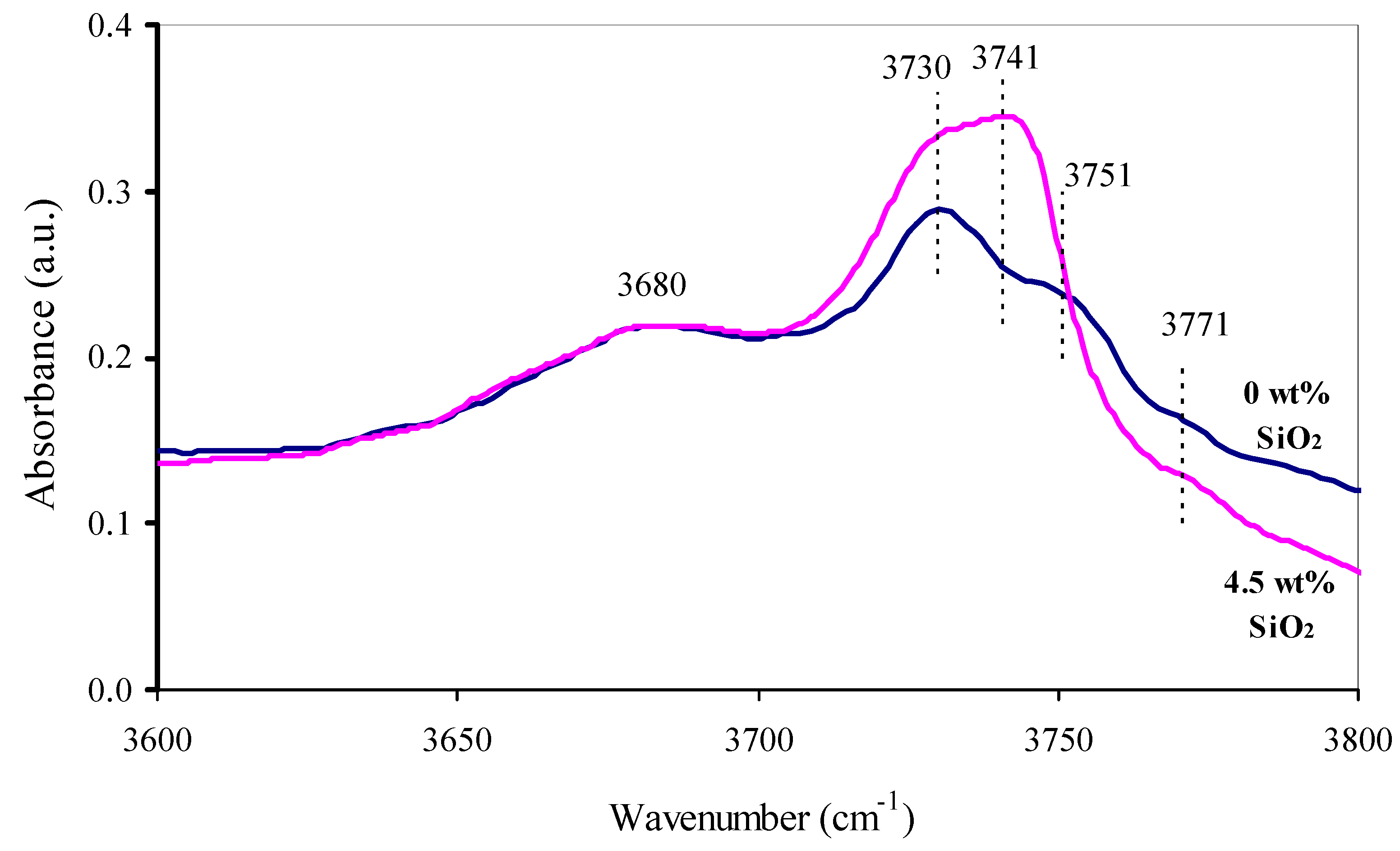
SiO2-modification of the support was carried out by its impregnation with an aqueous SiOii-sol and subsequent thermal handling at 800 °C. Introduction of silica in an amount of 2.five–vii.5 wt % does not bear upon the phase limerick of the support. In the X-ray diffraction patterns of all the samples (not shown in the current paper) the characteristic peaks of only γ-AliiOiii were identified. The absence of changes in the crystalline structure of the supports leads to the conclusion that the SiO2 is localized on the back up's surface. In the IR-spectrum of the SiO2-modified support the absorption band of Si–OH at 3741 cm−one [17,eighteen] appears with a decrease of the intensity of the bands at 3751 and 3771 cm−i (Al–OH bond vibrations [19,20]) (Figure 4). This likewise indicates that the SiO2 is distributed on the support surface.
On the surface of the modified supports silica is distributed in the course of SiO x -fragments Si(OSi)3O and Si(OSi)4. This is indicated by the occurrence of the signals at −101 and −125 ppm on the 29Si Magic Angle Spinning Nuclear Magnetic Resonance (MAS NMR) spectra (Figure v) [18,21,22,23,24].
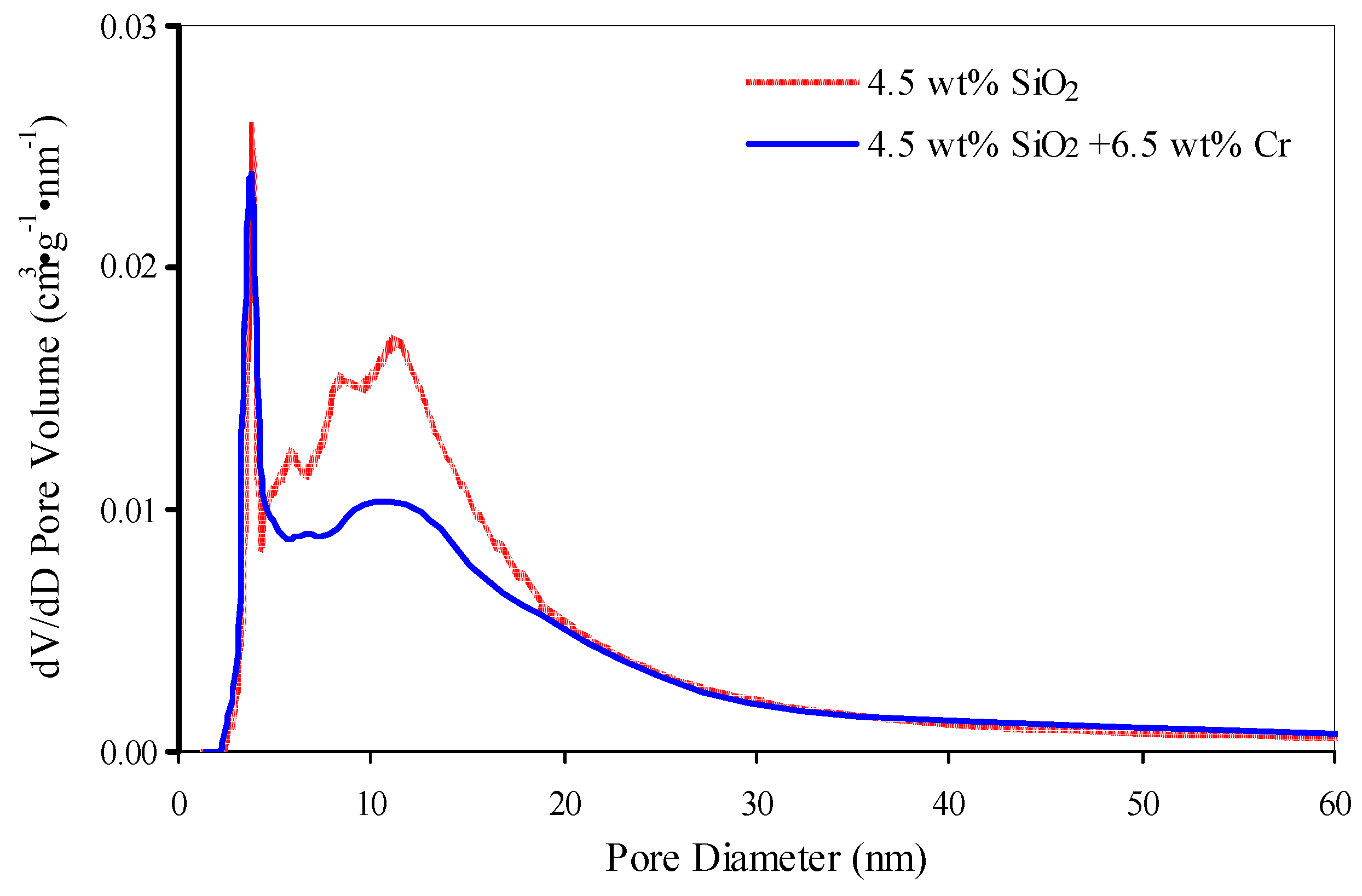
The distribution of the modifier on the surface leads to changes in the porous system of the supports. The volume of the pores with diameter less than x nm decreases from 0.08 to 0.06 cm3·g−i. SiO x -islands form additional porosity in the range of diameters ten–30 nm; the volume of these pores increases from 0.13 to 0.xvi cmiii·g−1 (Figure half dozen). At the same fourth dimension the specific surface area does non modify significantly (Table 2).
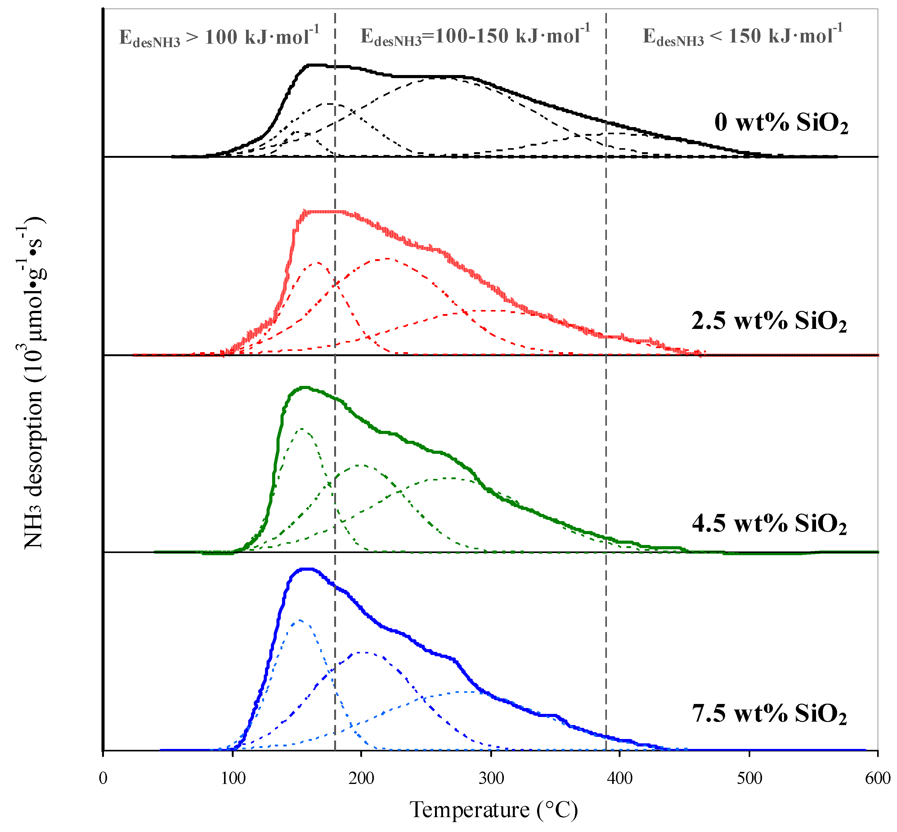
SiOtwo-modification of the support causes changes in the surface acerbity (Effigy 7, Table 3). It increases from 102.3 to 109.0–125.3 μmol·g−1 due to the germination of weak (E des.NHiii < 100 kJ·mol−one) and medium (E des.NH3 = 100–150 kJ·mol−ane) acid sites (Table 3). This is indicated by the growth of the NH3-TPD (temperature programmed desorption) profiles in the range 160–350 °C (Figure 7). Along with the germination of an additional amount of the weak and medium sites the concentration of stiff acid sites (with E des.NH3 > 150 kJ·mol−one) decreases (Table 3). This is indicated by the decrease in intensity of the high temperature component (400–500 °C) of the NHthree-TPD profile. The maximal temperature of ammonia desorption shifts to lower values (Figure 7) indicating a decrease in forcefulness of the acid sites.
It is likely that the acid sites formed are hydroxyl groups bonded to the silicon atoms and the Lewis acid sites of various structures [21,24]. For example, Iengo et al. [21] suggested, that the new acid sites are formed at the border of the SiO 10 -islands, where aluminum and silicon are arranged relative to each other in such a fashion, that the aluminum atoms are positively charged and partially neutralized by the negative charges of the silicates. The decrease in number of the stiff acid sites upon modification is probably due to them being covered by SiO 10 -islands.
2.2. Chromia-Alumina Catalyst
2.2.ane. Composition, Crystal and Pore Construction, Acerbity of Catalysts
On the ground of the initial alumina support it was established that surface concentration 10 atoms·nm−two provides both loftier activity and the absence of crystalline α-CrtwoOiii in the catalyst (Figure 8), which accelerate catalyst sintering and decreases its thermal stability (Table 4).
In the synthesized catalysts an optimum mass ratio of chromium to potassium was used (Cr/K = 8) which was established by Kataev [25] for alumina supports obtained by the sequential thermal-hydrothermal treatment of gibbsite. Potassium every bit a promoter performs several functions in chromia-alumina catalysts. It neutralizes the stiff acid sites [15] and thus decreases the activity of the catalyst in hydrocarbon smashing reactions (Tabular array 4). Potassium in catalyst forms potassium chromates at the expense of the low-active crystalline CriiO3 phase. These chromates are reduced to catalytically agile Cr(Three) phase in dehydrogenation conditions [xv,26]. However, an excessive amount of potassium poisons the catalyst due to the coverage of the active Cr(III) sites [26] and neutralization of the weak and medium acrid sites which adsorb alkane molecules [15]. Optimal potassium content depends non only on the surface area and acidity of the back up but also on the concentration of chromium because potassium as aluminate and chromates is distributed both on the open areas of alumina and on the CrtwoOthree particles [26].
The chromia-alumina catalysts with a surface concentration of chromium 10 atoms·nm−2 were synthesized on the SiO2-modified supports (Table five).
As a outcome of the chromium and potassium distribution in the pores of initial and SiO2-modified support (Effigy ix), specific surface surface area and pore volume subtract slightly-by 6–17 thousand2·g−1 and 0.04–0.06 cmiii·thou−1 respectively (Tabular array ane and Table five).
Introduction of 6.5 wt % chromium and 0.8 wt % potassium to supports decreases the number of acrid sites by fifteen.7–29.9 μmol·g−i (Table 3 and Table 6). SiO2 affects the acidity of the catalysts like to those of the supports: introduction of 2.5–seven.5 wt % SiOii increases the full acidity of goad due to the formation of an additional weak and medium acid sites; it too decreases the number of strong acid sites.
2.2.2. Active Component of Catalysts
Formation on the support surface of SiO ten -islands results in changes in the distribution of the active component. Modification of the support by two.5–vii.5 wt % SiO2 leads to a decrease of Cr(VI) content in the catalysts based on it.
Past diffuse reflectance UV-Vis spectroscopy it was found that chromium deposition on the SiOii-modified supports results in an increment of Cr(Three) content in comparing to the initial support. It tin be seen by the increase in intensity of the betoken at ~17,000 cm−i (Figure x) which corresponds to an electronic transition 4A2g→4T2g in the Cr(III)oct ion [26,27]. Increasing the Cr(3) content is consistent with the information of the iodometric titration, showing that the concentration of Cr(VI) (calculated as CrOiii) decreases from 2.v to 1.4 wt % with an increment of SiO2 content from 0 to vii.five wt % (Table 5). UV-Vis spectra also demonstrate a shift of the Cr(VI) signal at ~27,000 cm−1 [26,28,29] to the short-wavelength region and an increment in intensity of the complex Cr(III)-Cr(VI) indicate at ~22,000 cm−1 [26,27,28,29] (Figure 10). In combination these indicate a subtract in symmetry of surface chromates due to oligomerization of Cr(Vi) compounds [26].
The increment in Cr(III) content observed past UV-Vis spectroscopy and the oligomerization of surface Cr(Half dozen) compounds are consistent with the Raman-spectroscopy data. Here, the increase in SiO2 content results in the growth in intensity of the signal at ~550 cm−one, respective to the vibrations of the Cr(III)oct–O bond [26,30,31]; the intensity of hydrated dichromate signals at 906 and 948 cm−i [28,30] decreases; the typical signals of dehydrated polychromates at 850–900 and m cm−1 [28,30,31,32] too appear (Figure xi).
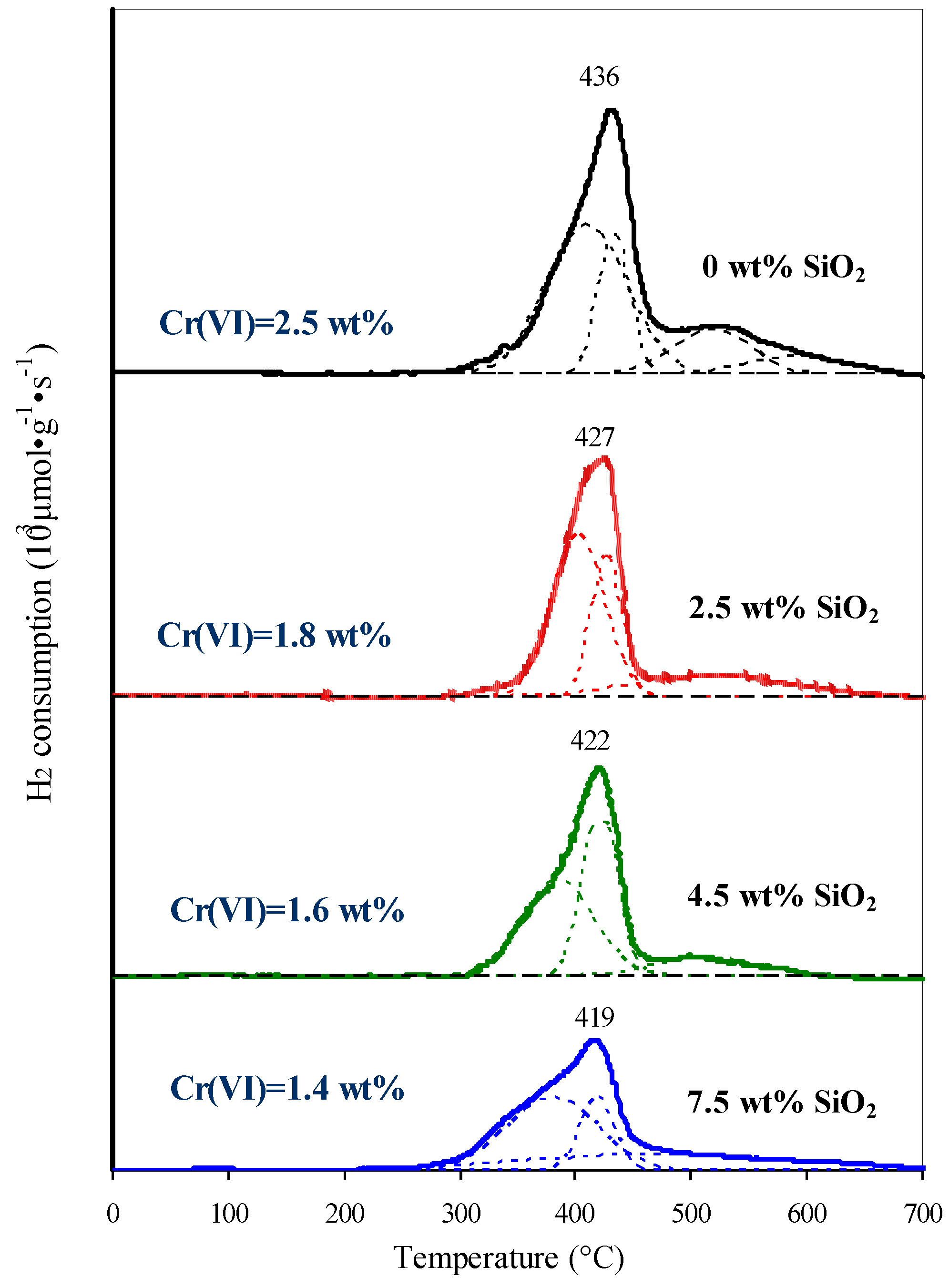
Decreasing Cr(Vi) content and the simultaneous oligomerization of chromates indicates a subtract of stabilization of the chromates by the support surface through X–O–Cr (10 = Al, Si) bonds. This is also supported past the temperature-programmed reduction of catalysts. All H2-TPR profiles are decomposed into 3–4 Gaussian components which correspond to the chromates with dissimilar degrees of bounden to the surface. The higher the temperature of chromate reduction the greater is the number of X–O–Cr bonds per 1 chromium atom [26,33]. Therefore, the low-temperature components (at 300–450 °C and 400–450 °C) most probable represent to polychromates, and the loftier-temperature components (at 450–600 °C and 500–650 °C) stand for to mono- and dichromates. The introduction of 2.5–7.v wt % SiO2 leads to the redistribution of the hydrogen consumption temperature: the depression temperature component of the H2-TPR profile (in the region 300–400 °C) increases and the high temperature component (in the range 500–600 °C) decreases. The Gaussian component of the H2-TPR profile in the region 550–600 °C, corresponding to monochromates with the highest degree of interaction with the back up surface, disappears. The maximum on the H2-TPR profiles sequentially shifts from 436 to 419 °C (Effigy 12).
The decrease in interaction betwixt the back up and the active component is due to the changes in hydroxyl comprehend of the support. The isoelectronic indicate (IEP) of alumina is vii.2–8.vi, and the IEP of silica is 2.0–3.9 [34,35,36]. This is caused by the predominance of the following reactions on the surface of the hydrated supports [34,36]:
–Al–OH + H+ ↔ –AlOHii +
Due to a larger number of basic sites on the alumina surface during deposition of the active component from an aqueous solution of chromic acid and subsequent heat treatment, a greater interaction of chromate ions with Al2Oiii rather than with SiOii and SiOii–AliiO3 is observed [37]. The interaction of chromate ions with the alumina surface is complex [35] and consists of:
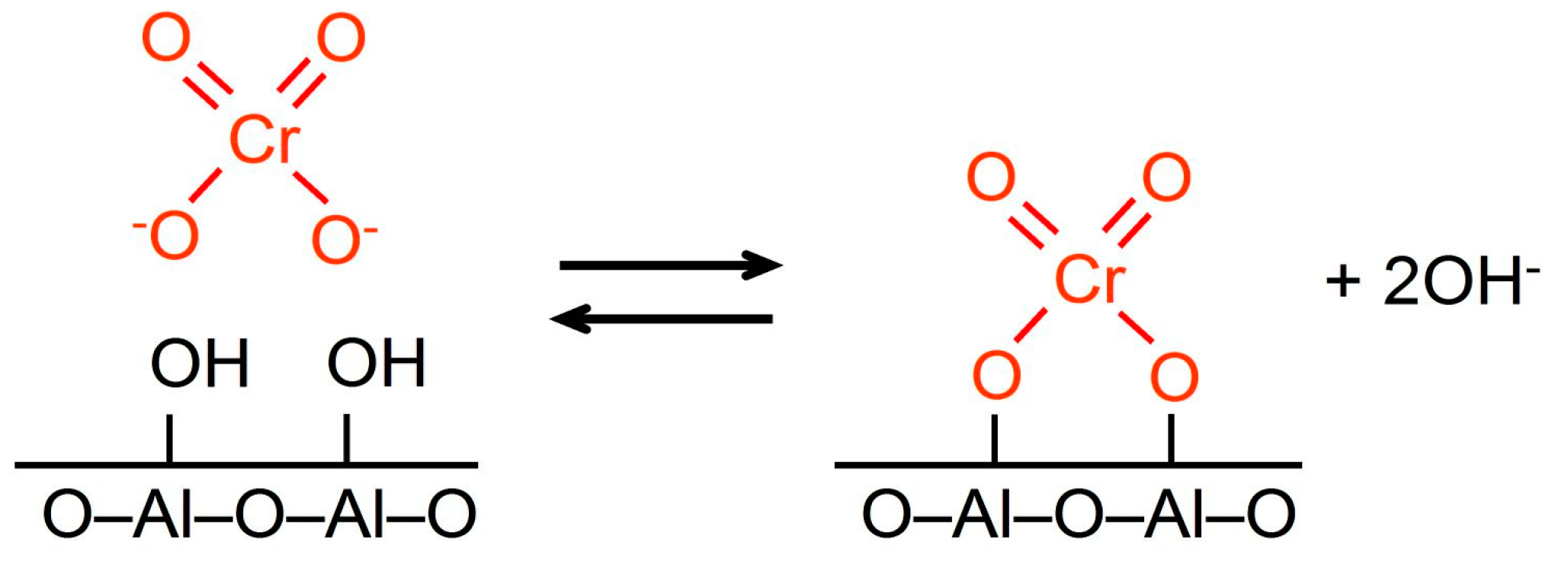
(1) acid-base reaction between the neutral surface hydroxyl groups and chromate anions (Scheme two):
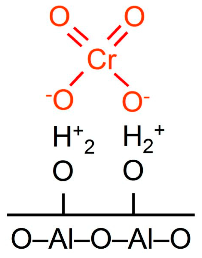
(2) electrostatic attraction (Scheme 3) between the chromate ions and the positive-charged surface sites (in the inner Helmholtz airplane of the electrical double layer) which is formed by protonation of the surface hydroxyl groups (Reaction (1)) [35]:
Therefore, on the surface of alumina predominantly mono- and dichromate anions are stabilized (Scheme iv).
As is shown the formation of SiO10-islands on the alumina surface leads to diminution in interaction between Cr(VI) compounds and the support. It may occur due to the following reasons:
–subtract in the number of surface basic hydroxyls capable of acid-base of operations reaction (Scheme ii) with chromate ions;
–SiOii introduction results in a drop of the pH of the electric double layer. This in plow leads to a shift of the equilibrium of Reactions (3)–(five) to the correct, towards formation of polynuclear chromate ions [31].
2CrOiv two− + 2H+ ↔ CriiOseven 2− + H2O
3CriiOvii 2− + 2H+ ↔ 2Cr3Oten ii− + HiiO
4Cr3O10 two− + 2H+ ↔ 3Cr4O13 two− + H2O
–according to Reaction (2) the function of the inner Helmholtz plane becomes negatively charged which results in the electrostatic allure between support surface and chromate ions diminishing.
A decrease in the number of Cr–O–10 (10 = Al, Si) bonds leads to the stabilization of the polychromate ions and polynuclear [–Cr(III)–O–Cr(Three)–] northward ions (also chosen amorphous Cr2Othree [26] or Cr2O3-clusters [28]) (Scheme 4) by the SiOtwo-modified support surface afterward thermal activation of the goad. A similar issue of SiO2 has too been reported by Weckhuysen et al. [29]; at the transition from Al2O3 to aluminosilicate (with 40 wt % SiO2) the chromate/dichromate band intensity ratio on the UV-Vis spectra of the samples calcined at 550 °C decreased from ∞ to 2.xviii. Weckhuysen et al. [38] reported that in SiO2 with 0.two wt % Cr calcined at 720 °C, Cr(III) ions were identified past UV-Vis spectroscopy, whereas for the same amount of chromium on alumina, Cr(III) ions were not observed.
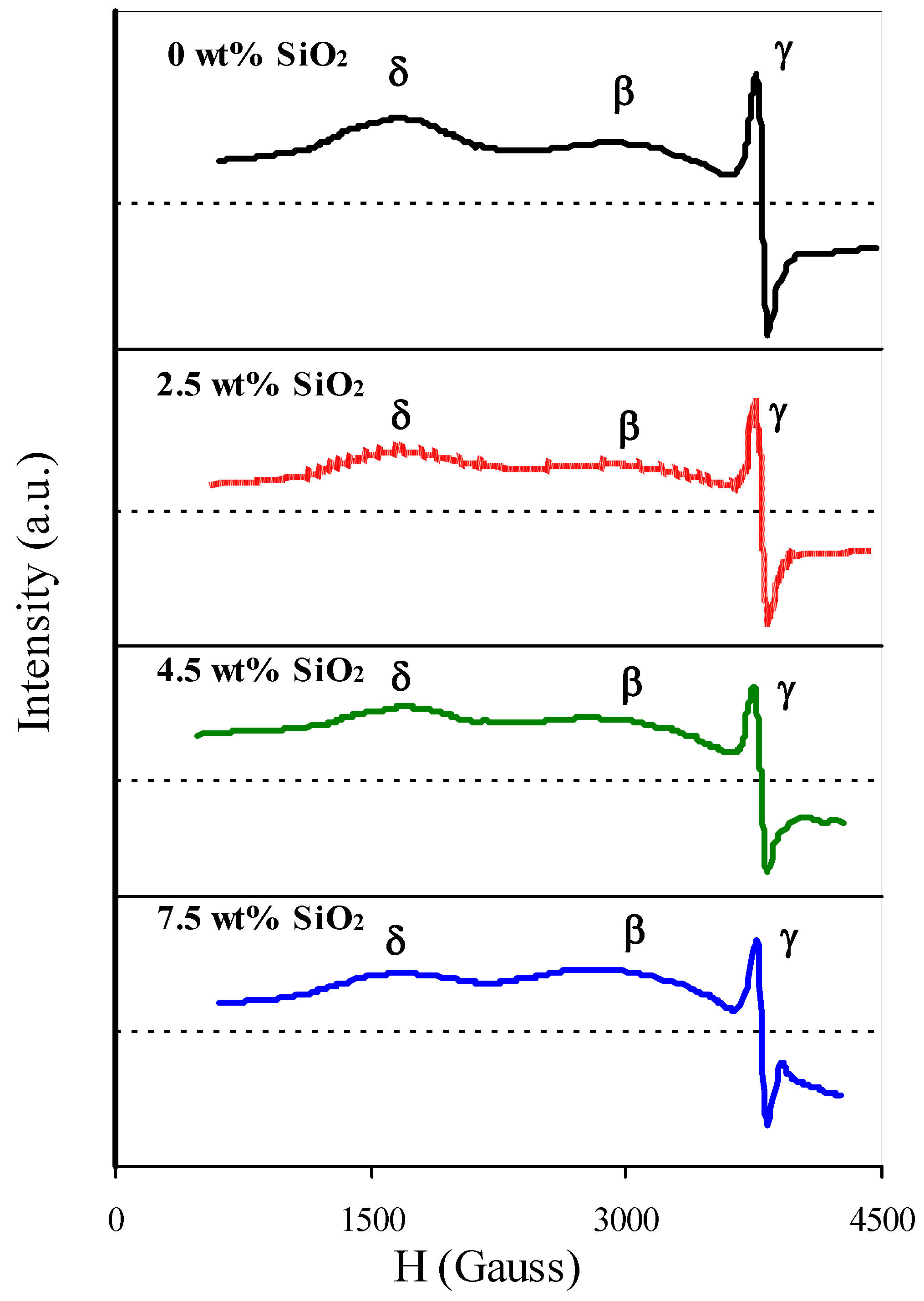
Increasing interaction between Cr(Three) ions was also confirmed by EPR-spectroscopy. Upon introduction of SiO2 the intensity of the δ-signal component at g = 3.8–4.0, corresponding to isolated Cr(Iii) ions [39], decreases while the intensity of β-indicate with chiliad = 1.98 and ΔH = 1400–1600 G, respective to magnetically concentrated Cr(3) ions [28,39], increases (Effigy 13).
2.ii.3. Isobutane Dehydrogenation Performance of Catalysts
Chromia-alumina catalysts were tested in isobutane dehydrogenation at 570 °C. The curves of dehydrogenation and cracking rate versus time on stream are shown on Figure 14a,b, respectively. All the curves on Figure 14a show the maxima as a function of fourth dimension on stream. In all the cases at the initial phase of the dehydrogenation cycle (for the outset 30–55 min) an increment of catalyst dehydrogenation activity by 8%–9.5% is observed (Effigy 14a); this is the goad development period. Equally we know [40,41] during catalyst development the surface stabilized Cr(Six) compounds are reduced by hydrocarbons to additional catalytically agile Cr(3) compounds. Decrease of the dehydrogenation rate at the last stage of the cycle is due to the goad coking. The subtract of the neat rate during the starting time 30 min (Figure 14b) is also caused by covering of the acid sites by coke deposits [xv].
The increment in the content of amorphous Cr2O3 phase, which is the well-nigh active in the dehydrogenation of calorie-free alkanes [26], and the formation of polychromates which too reduce to amorphous CriiOiii, causes an increment in dehydrogenation activity of catalysts based on SiO2-modified supports (Figure 14a). The average dehydrogenation activity increases past 10%–14%—from 2.9 to iii.2–3.3 μmol CfourH10·gtrue cat −1·southward−one. At the same time the catalyst development period diminishes due to a subtract in the Cr(VI) content. The ascension in dehydrogenation activity with the increase in the polynuclear Cr(III) ions content is consequent with the results of the kinetic studies by Airaksinen et al. [42] and Carra et al [43]. Co-ordinate to these works the dehydrogenation of one molecule of butane proceeds at two active sites.
A decrease in the number of strong acrid sites upon SiO2-modification of support leads to a decrease in cracking rate on catalysts with two.v–7.5 wt % SiO2 (Figure 14b). The average groovy rate decreases by xviii%–34%—from 0.29 to 0.xix–0.24 μmol (Cone–Cthree)·mtrue cat −one·s−1.
3. Materials and Methods
3.one. Preparation of Supports and Catalysts
Microspherical (40–200 μm) boehmite support prepared by consecutive thermal and hydrothermal treatment of aluminum trihydroxide (GD00 grade, produced by Bogoslovsk Aluminum Smelter, Krasnoturyinsk city, Russian federation) under industrial atmospheric condition [11] in an autoclave for 3 h at 195 °C (Chemical Found Karpov, Mendeleyevsk city, Russia), was used for the synthesis of alumina supports and chromia-alumina catalysts. According to thermogravimetry the phase composition of the support precursor is the following: boehmite—96.0 wt %, gibbsite—3.0 wt %, Al2Othree—ane.0 wt %.
SiOtwo was introduced into the support by incipient wetness impregnation with a water silica sol ("Leiksil" brand produced by "Compas" Scientific and Technical Eye, Kazan city, Russia).
The goad was prepared by incipient wetness impregnation of the support with an aqueous solution of chromic acrid and potassium carbonate, followed by drying under vacuum. Then the catalyst was activated by thermal treatment in a muffle furnace at 750 °C for 4 h.
3.2. Characterization of Supports and Catalysts
Thermogravimetric analysis was performed with a STA-449C (Netzsch, Selb, Germany) combined thermogravimetric and differential scanning calorimetric (DSC) analyzer coupled with an Aeolos QMS 403 quadruple mass spectrometer (Netzsch, Selb, Germany) in a temperature range of thirty–1000 °C at a heating rate of 10 °C. min−1 in a flow of argon. The concentrations of aluminum hydroxide phases were calculated from the corporeality of water released in their dehydration.
Scanning electron microscopy was performed on an EVO l XVP (Carl Zeiss, Oberkochen, Germany) electron microscope.
The elemental composition of the catalysts was determined by Ten-ray fluorescence spectroscopy on a Clever C31 musical instrument (ELERAN, Elektrostal, Russia).
Powder 10-ray diffraction measurements were carried out using a DRON-2 diffractometer (Burevestnik, Petrograd, Russia). The patterns were obtained using CuKα radiations and graphite monochromator (λ = 1.54187 Å) at 30 kV and 15 mA. The identification of unlike crystalline phases in the samples was performed by comparing the data with the Joint Committee for Pulverization Diffraction Standards (JCPDS) files. The crystallite size of the boehmite stage was calculated using the Selyakov–Scherrer Equation. The error in determining the crystallite size was 10%.
Specific surface (S sp) and pore volume (5 p) of samples were determined from the Northward2 physisorption measurements at 196 °C using an universal Autosorb-iQ analyzer (Quantachrome, Boynton Embankment, FL, U.s.). Prior to measurement, the sample was outgassed for 1 h at 150 °C (for boehmite precursor) or for iii h at 300 °C (for alumina supports and catalysts). S sp and V p were calculated according to the Brunauer-Emmett-Teller method. The pore diameter distribution was calculated by the desorption branch of isotherm using the standard Barrett–Joyner–Halenda method.
The 29Si MAS NMR spectra of supports were recorded at room temperature on an Avance 400 spectrometer (Bruker, Ettlingen, Germany) operating at frequencies of 79.5 MHz with spectral resolution 48.83 Hz. The sample rotation frequency was 5 kHz.
The IR spectra of supports were measured on a VERTEX 70 (Bruker, Ettlingen, Deutschland) instrument fitted with a mercury−cadmium−telluride detector. The measurements were done in transmission mode using a Harrick high temperature cell. A background spectrum and the spectra were measured at 480 °C and a residual pressure of less than x−3 mbar with a resolution of 1 cm−1 and averaged past 128 scans. For the IR analysis, samples were prepared in a tablet-shape of twenty mg; optical density was 20 mg·cm−2.
Hexavalent chromium concentration in the catalyst was determined by dissolution of Cr(VI) in sulfuric acid and subsequent volumetric titration with the iodometric method.
UV-Vis diffuse reflectance spectra of the catalysts were recorded using a V-650 spectrophotometer (Jasco, Tokyo, Japan) equipped with an integrating sphere ISV-722 (Jasco, Tokyo, Nihon). A BaSO4 plate was used as the reference. Spectra were recorded in the wavenumber range 12,500–50,000 cm−1 with the spectral resolution 2 nm. UV-Vis-spectra were deconvoluted into Gaussian bands to decide the positions and intensities of the bands' maximums.
Raman spectra of catalysts were recorded using a dispersion Raman-microspectrophotometer Nicolet Almega XR (Thermo Fisher Scientific, Waltham, MA, U.s.a.). The 532 nm line of a Nd-YAG laser was used as an excitation. The spectra were recorded in the wavenumber range 100–1100 cm−i with the spectral resolution two cm−1. Each spectrum was received by averaging 10 exposures on 10 south.
EPR measurements were fabricated at the temperature of −196 °C on a RE-1306 EPR-spectrometer (Institute of Belittling Instrumentation of Russian University of Sciences, St. petersburg, Russian federation) with a working frequency nine.37 GHz and 100 kHz magnetic field modulation. Diphenylpicrylhydrazyl (yard = 2.0036) was used as reference for 1000-value determination.
NH3-TPD and H2-TPR measurements were carried out on the ChemBET Pulsar TPR/TPD (Quantachrome, Boynton Beach, FL, The states). Earlier NH3-TPD measurement the sample was degassed at 600 °C for 2 h in a helium flow. The adsorption step is carried out in an ammonia flow at 100 °C for thirty min. So the physically sorbed ammonia was removed with helium at 100 °C for 30 min and the sample was cooled to a room temperature in the helium flow. Temperature programmed desorption was performed from room temperature to 700 °C at a heating rate of ten °C·min−1. The forcefulness of the acid sites was evaluated by the temperature of ammonia desorption [44]. A temperature of 175 °C corresponds to ammonia desorption energy of 100 kJ∙mol−i and a temperature of 380 °C to the desorption energy 150 kJ∙mol−1. Acid sites with ammonia desorption energy lower than 100 kJ∙mol−one were attributed to weak ones, while the sites with desorption energies of 100–150 kJ∙mol−1 and higher than 150 kJ∙mol−i were attributed to medium and strong sites respectively. The number of weak, medium and potent acid sites was calculated from the area under the NH3-TPD profiles in the temperature ranges <175 °C, 175–380 °C and >380 °C respectively.
Before H2-TPR measurement the catalyst was heated to 650 °C and held at this temperature for 60 min in a flow of a gas mixture (v vol% Otwo + 95 vol% Ntwo). Then the goad was cooled downwards to room temperature in the helium menstruation. Temperature programmed reduction was performed from room temperature to 700 °C at a heating charge per unit of 10 °C·min−1. NH3-TPD and Htwo-TPR profiles were Gauss fitted using the TPRWin software (version 3.52, Quantachrome, Boynton Beach, FL, U.s.a., 2012).
3.three. Catalyst Testing
The catalysts were tested in the reaction of isobutane dehydrogenation in a steel stock-still bed reactor of 10 mm internal diameter under atmospheric pressure. An amount of 2 grand of fresh catalyst (sieve fraction 40–200 μm) was filled into the reactor. The catalyst was heated at 5 °C·min−one to 650 °C in an air period (60 mL·min−1) followed by flushing with air for 30 min at the aforementioned temperature. The goad was cooled in air to 570 °C and flushed with argon for 15 min at that temperature. Then a mixture of thirty vol% C4Hten in Ar was fed at a rate of threescore mL·min−1 at the same reaction temperature. The reaction was run for 130 min followed by goad regeneration in an air flow for threescore min at 650 °C. The regeneration/dehydrogenation cycles were repeated three times.
The hydrocarbon composition of feed and reaction products were analyzed by gas chromatography on a GH-thousand instrument (Chromos, Dzerzhinsk, Russia) with a flame-ionization detector and a capillary VP-Alumina/KCl column (VICI Valco, Houston, TX, Usa). The concentrations of H2, CH4, and CO were determined with the use of a cavalcade filled by 13× molecular sieves on a GH-g appliance with a thermal conductivity detector.
Based on of the results of chromatographic analysis the rates of i-C4H10 dehydrogenation and cracking of hydrocarbons were calculated using Equations (6) and (seven), respectively.
where 10(iC4H10) is the isobutane conversion, %; F is the feed rate of isobutane, mole·h−1; grand cat is the weight of goad, k; C CH4 , C C2H6 , C CtwoH4 , C CiiiH8 , C CiiiH6 are the concentrations of methane, ethane, ethylene, propane, propylene respectively in the reaction products, vol%; Five outlet is the volumetric flow of the reaction products, mL·h−1.
iv. Conclusions
The distribution of SiO2 and its effect on the construction and acidity of the alumina back up, as well as the effect of SiOtwo on the active component and the operation in isobutane dehydrogenation of chromia-alumina catalyst were investigated. It was shown that SiOtwo in an amount of 2.5–7.five wt % is distributed on the surface of alumina in the course of Si(OSi)4 and Si(OSi)3(O–) compounds. These SiO x -islands on the support produce additional porosity with a pore range x–30 nm, also equally boosted weak and medium acrid sites. At the same time SiO2-modification causes a decrease in the number of strong acrid sites.
Upon introduction of the agile component, the SiO x -islands diminish the interaction of chromate ions with the back up surface; as a consequence polychromates are the compounds predominantly stabilized on the support. During thermal activation of the catalyst these polychromates are reduced to a phase of amorphous Cr2Oiii. This results in the increase of the goad action in the isobutane dehydrogenation. At the same time, the subtract in the number of strong acrid sites in SiO2-modified catalysts leads to a diminution of its activity in hydrocarbon cracking reactions.
Acknowledgments
The work was performed co-ordinate to the Russian Government Program of Competitive Growth of Kazan Federal Academy.
Author Contributions
Southward.R.E and A.A.L conceived and designed the experiments; G.East.B. and A.N.M. performed the experiments. All authors participated in the analysis of the information and writing of the paper. G.East.B., A.N.1000. and S.R.E. proofread the manuscript.
Conflicts of Involvement
The authors declare no conflict of interest.
References
- Voloshina, O.A.; Nazarova, Eastward.A.; Petrov, I.M. Obzor Rynka Promyshlennyh Katalyzatorov v Rossii (Review of Industrial Catalyst's Market in Russia); INFOMINE Research Grouping: Moscow, Russian federation, 2008; pp. 213–218. [Google Scholar]
- Sattler, J.J.H.B.; Ruiz-Martinez, J.; Santillan-Jimenez, E.; Weckhuysen, B.Thou. Catalytic dehydrogenation of low-cal alkanes on metals and metal oxides. Chem. Rev. 2014, 114, 10613–10653. [Google Scholar] [CrossRef] [PubMed]
- Kolesnikov, I.M. Kataliz i Proizvodstvo Katalizatorov (Catalysis and Catalysts Product); Tehnika: Moscow, Russia, 2004; pp. 314–315. [Google Scholar]
- Pakhomov, North.A.; Parakhin, O.A.; Nemykina, Due east.I.; Danilevich, Five.V.; Chernov, M.P.; Pecherichenko, V.A. Microspherical chromium oxide/alumina goad KDM for fluidized bed isobutane dehydrogenation: Development and industrial awarding feel. Catal. Ind. 2012, iv, 298–307. [Google Scholar] [CrossRef]
- Egorova, S.R.; Kataev, A.N.; Bekmukhamedov, G.E.; Lamberov, A.A.; Gil'mullin, R.R.; Nesterov, O.N. Development of engineering for the production of microspherical aluminum oxide supporter for the paraffin dehydrogenation catalyst. Catal. Ind. 2009, 1, 381–390. [Google Scholar] [CrossRef]
- Zeeshan, Northward. Light alkane dehydrogenation to light olefin technologies: A comprehensive review. Rev. Chem. Eng. 2015, 31, 413–436. [Google Scholar]
- Sanfilippo, D.; Miracca, I. Dehydrogenation of paraffins: synergies between catalyst blueprint and reactor engineering. Catal. Today 2006, 111, 133–139. [Google Scholar] [CrossRef]
- Korhonen, Due south.T.; Airaksinen, S.K.G.; Banares, M.A.; Krause, A.O.I. Isobutane dehydrogenation on zirconia-, alumina-, and zirconia/alumina-supported chromia catalysts. Appl. Catal. A 2007, 333, 30–41. [Google Scholar] [CrossRef]
- Bugrova, T.A.; Litvyakova, Northward.N.; Mamontov, 1000.V. Consequence of zirconia additives on the activity of the Cr/SiOtwo catalyst in isobutane dehydrogenation. Kinet. Catal. 2015, 56, 758–763. [Google Scholar] [CrossRef]
- Jiménez-López, A.; Rodr'ıguez-Castellón, Due east.; Maireles-Torres, P.; D'ıaz, Fifty.; Mérida-Robles, J. Chromium oxide supported on zirconium- and lanthanum-doped mesoporous silica for oxidative dehydrogenation of propane. Appl. Catal. A 2001, 218, 295–306. [Google Scholar] [CrossRef]
- Hoang, D.L.; Dittmar, A.; Radnik, J.; Brzezinka, K.-Due west.; Witke, K. Redox behaviour of La-Cr compounds formed in CrO x /La2O3 mixed oxides and CrO x /LaiiO3/ZrOtwo catalysts. Appl. Catal. A 2003, 239, 95–110. [Google Scholar] [CrossRef]
- Cabrera, F.; Ardissone, D.; Gorriz, O.F. Dehydrogenation of propane on chromia/alumina catalysts promoted by tin. Catal. Today 2008, 133–135, 800–804. [Google Scholar] [CrossRef]
- Babenko, V.S.; Pakhomov, North.A.; Buyanov, R.A. Investigation of the thermal stability of the chromia–alumina catalysts for the process of the one-phase dehydrogenation of n-butane. Catal. Ind. 2009, i, 43–49. [Google Scholar] [CrossRef]
- Buonomo, F.; Jezzi, R.; Notari, B.; Kotelnikov, G.R.; Michailov, K.R.; Patanov, 5.A. Method for the Training of a Catalyst for the Dehydrogenation of C3-C5 paraffins. U.S. Patent 4746643, 24 May 1988. [Google Scholar]
- Rombi, Eastward.; Cutrufello, M.One thousand.; Solinas, V.; De Rossi, S.; Ferraris, G.; Pistone, A. Effects of potassium addition on the acidity and reducibility of chromia/alumina dehydrogenation catalysts. Appl. Catal. A 2003, 251, 255–266. [Google Scholar] [CrossRef]
- Paukshtis, E.A. Infrakrasnaya Spectroscopya five Geterogennom Kislotno-Osnovnom Katalize (IR-spectroscopy in Heterogeneous Acrid-Base Catalysis); Nauka: Novosibirsk, Russia, 1992; pp. 78–92. [Google Scholar]
- Morrow, B.A.; Cody, I.A. Infrared studies of reactions on oxide surfaces. 6. Agile sites on dehydroxylated silica for the chemisorption of ammonia and water. J. Phys. Chem. 1976, 80, 1998–2004. [Google Scholar] [CrossRef]
- Lindblad, One thousand.; Root, A. Atomically controlled training of silica on alumina. Stud. Surf. Sci. Catal. 1998, 118, 817–826. [Google Scholar]
- Lundie, D.T.; McInroy, A.R.; Marshall, R.; Winfield, J.M.; Jones, P.; Dudman, C.C.; Parker, S.F.; Mitchell, C.; Lennon, D. Improved clarification of the surface acidity of η-alumina. J. Phys. Chem. B. 2005, 109, 11592–11601. [Google Scholar] [CrossRef] [PubMed]
- Srinivasan, S.; Narayanan, C.R.; Datye, A.K. The role of sodium and structure on the catalytic behavior of alumina: II. IR spectroscopy. Appl. Catal. A 1995, 132, 289–308. [Google Scholar] [CrossRef]
- Iengo, P.; Di Serio, M.; Solinas, 5.; Gazzoli, D.; Salvio, One thousand.; Santacesaria, E. Preparation and properties of new acid catalysts obtained by grafting alkoxides and derivatives on the well-nigh mutual supports. Part II: Grafting zirconium and silicon alkoxides on γ-alumina. Appl. Catal. A 1998, 170, 225–244. [Google Scholar] [CrossRef]
- McMillan, M.A.; Brinen, J.S.; Carruhers, J.D.; Haller, G.L. 29Si NMR investigation of the construction of amorphous silica-alumina supports. Colloids Surf. 1989, 38, 133–148. [Google Scholar] [CrossRef]
- Sato, Due south.; Sodesawa, T.; Nozaki, F.; Shoji, H. Solid-state NMR of silica-alumina prepared past chemical vapor deposition. J. Mol. Catal. 1991, 66, 343–355. [Google Scholar] [CrossRef]
- Finocchio, Due east.; Busca, G.; Rossini, South.; Cornaro, U.; Piccoli, Five.; Miglio, R. FT-IR characterization of silicated aluminas, active olefin skeletal isomerization catalysts. Catal. Today 1997, 33, 335–352. [Google Scholar] [CrossRef]
- Kataev, A.N. Germination of a Monophase Microspherical Alumina Support and a Catalyst for Isobutane Dehydrogenation in the Industrial Synthesis. Ph.D. Thesis, Kazan State Technological University, Kazan, Russia, 2009; p. 106. [Google Scholar]
- Cavani, F.; Koutyrev, M.; Trifiro, F.; Bartolini, A.; Ghisletti, D.; Iezzi, R.; Santucci, A.; Del Piero, Thousand. Chemical and physical characterization of alumina-supported chromia-based catalysts and their activity in dehydrogenation of isobutane. J. Catal. 1996, 158, 236–250. [Google Scholar] [CrossRef]
- Reinen, D. Ligand-field spectroscopy and chemical bonding in Crthree+-containing oxidic solids. Struct. Bond. 1969, 6, 30–51. [Google Scholar]
- Weckhuysen, B.M.; Wachs, I.E.; Schoonheyd, R.A. Surface chemical science and spectroscopy of chromium in inorganic oxides. Chem. Rev. 1996, 96, 3327–3349. [Google Scholar] [CrossRef] [PubMed]
- Weckhuysen, B.Yard.; De Ridder, 50.M.; Schoonheydt, R.A. A quantitative diffuse reflectance spectroscopy report of supported chromium catalysts. J. Phys. Chem. 1993, 97, 4756–4763. [Google Scholar] [CrossRef]
- Vuurman, M.A.; Hardcastle, F.D.; Wachs, I.E. Characterization of CrO3/A1twoOiii catalysts under ambient conditions: influence of coverage and calcination temperature. J. Mol. Catal. 1993, 84, 193–205. [Google Scholar] [CrossRef]
- Vuurman, Grand.A.; Stufkens, D.J.; Oskam, A. Raman spectra of chromium oxide species in CrO3/Al2O3 catalysts. J. Mol. Catal. 1990, threescore, 83–98. [Google Scholar] [CrossRef]
- Mentasty, 50.R.; Gorriz, O.F.; Cadus, L.East. Chromium oxide supported on different AltwoO3 supports: Catalytic propane dehydrogenation. Ind. Eng. Chem. Res. 1999, 38, 396–404. [Google Scholar] [CrossRef]
- Kanervo, J.M.; Krause, A.O.I. Characterisation of supported chromium oxide catalysts by kinetic analysis of H2-TPR data. J. Catal. 2002, 207, 57–65. [Google Scholar] [CrossRef]
- Parks, K.A. The isoelectric points of solid oxides, solid hydroxides and aqueous hydroxo-complex systems. Chem. Rev. 1965, 65, 177–198. [Google Scholar] [CrossRef]
- Spanos, Northward.; Slavov, S.; Kordulis, Ch.; Lycourghiotis, A. Mechanism of degradation of the CrO4 ii−, HCrOfour −, and Cr2O7 2− ions on the γ-alumina surface. Langmuir 1994, x, 3134–3147. [Google Scholar] [CrossRef]
- Anderson, J.R. Structura Metallicheskih Katalizatorov (Structure of Metallic Catalysts); Mir: Moscow, Russia, 1978; pp. 40–46. [Google Scholar]
- Weckhuysen, B.Chiliad.; De Ridder, L.K.; Grobet, R.J.; Schoonheydt, R.A. Redox behavior and dispersion of supported chromium catalysts. J. Phys. Chem. 1995, 99, 320–326. [Google Scholar] [CrossRef]
- Weckhuysen, B.M.; Verberckmoes, A.A.; Buttiens, A.L.; Schoonheydt, R.A. Diffuse reflectance spectroscopy study of the thermal genesis and molecular structure of chromium-supported catalysts. J. Phys. Chem. 1994, 98, 579–584. [Google Scholar] [CrossRef]
- Puurunen, R.L.; Weckhuysen, B.Thou. Spectroscopic report on the irreversible deactivation of chromia/alumina dehydrogenation catalysts. J. Catal. 2002, 210, 418–430. [Google Scholar] [CrossRef]
- Weckhuysen, B.Thou.; Verberckmoes, A.A.; Debaere, J.; Ooms, Grand.; Langhans, I.; Schoonheydt, R.A. In situ UV-Vis lengthened reflectance spectroscopy—On line activity measurements of supported chromium oxide catalysts: relating isobutane dehydrogenation activity with Cr-speciation via experimental blueprint. J. Mol. Catal. A Chem. 2000, 151, 115–131. [Google Scholar] [CrossRef]
- Weckhuysen, B.M.; Bensalem, A.; Schoonheydt, R.A. In situ UV-VIS diffuse reflectance spectroscopy-on-line activity measurements. Significance of Cr n+species (n = two, three and 6) in n-butane dehydrogenation catalyzed by supported chromium oxide catalysts. J. Chem. Soc. Faraday Trans. 1998, 94, 2011–2014. [Google Scholar] [CrossRef]
- Airaksinen, S.M.Thou.; Harlin, 1000.E.; Krause, A.O.I. Kinetic modeling of dehydrogenation of isobutane on chromia/alumina catalyst. Ind. Eng. Chem. Res. 2002, 41, 5619–5626. [Google Scholar] [CrossRef]
- Carrà, S.; Forni, L.; Vintani, C. Kinetics and mechanism in catalytic dehydrogenation of n-butane over chromia-alumina. J. Catal. 1967, 9, 154–165. [Google Scholar] [CrossRef]
- Yushchenko, V.5. Calculation of the acidity spectra of catalysts from temperature-programmed ammonia desorption data. J. Phys. Chem. (Zhurnal Fizicheskoi Khimii) 1997, 71, 628–632. [Google Scholar]
Scheme i. Production of alumina precursor.
Scheme 1. Production of alumina precursor.

Figure i. Scanning electron microscopy (SEM) image of the microspherical support.
Figure 1. Scanning electron microscopy (SEM) image of the microspherical back up.
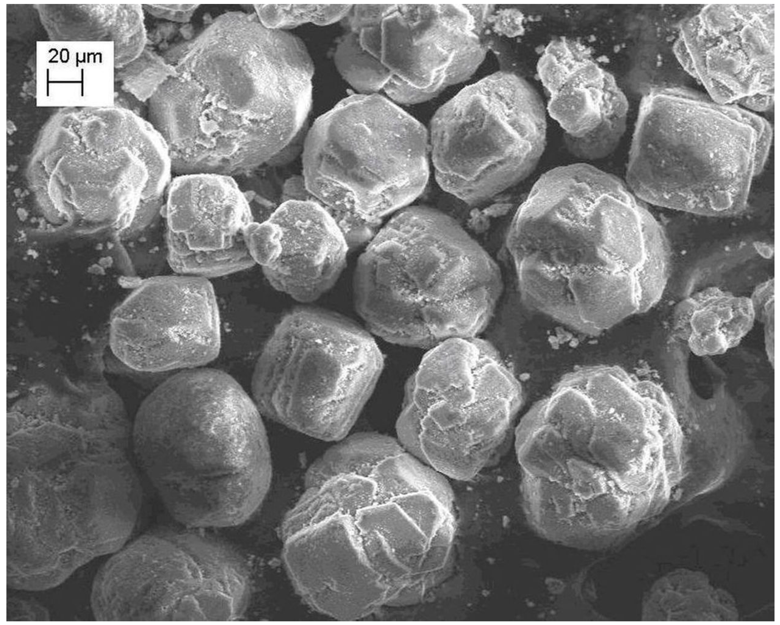
Figure 2. X-ray diffraction patterns of precursor of alumina and alumina support, obtained at 800 °C.
Figure 2. Ten-ray diffraction patterns of precursor of alumina and alumina support, obtained at 800 °C.
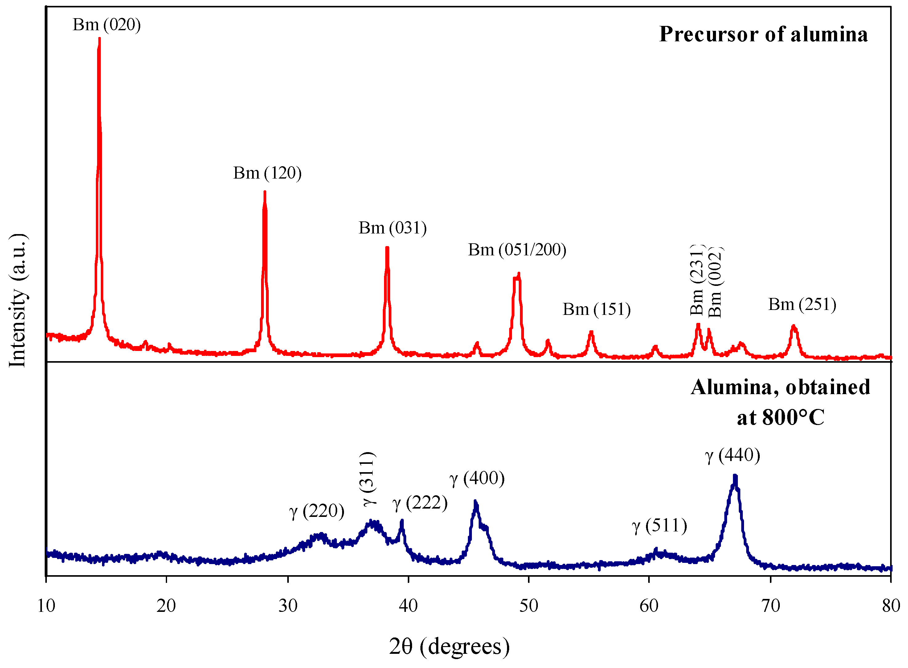
Figure 3. Pore size distribution for precursor of alumina and alumina supports, obtained at 750 °C and 850 °C.
Effigy 3. Pore size distribution for precursor of alumina and alumina supports, obtained at 750 °C and 850 °C.
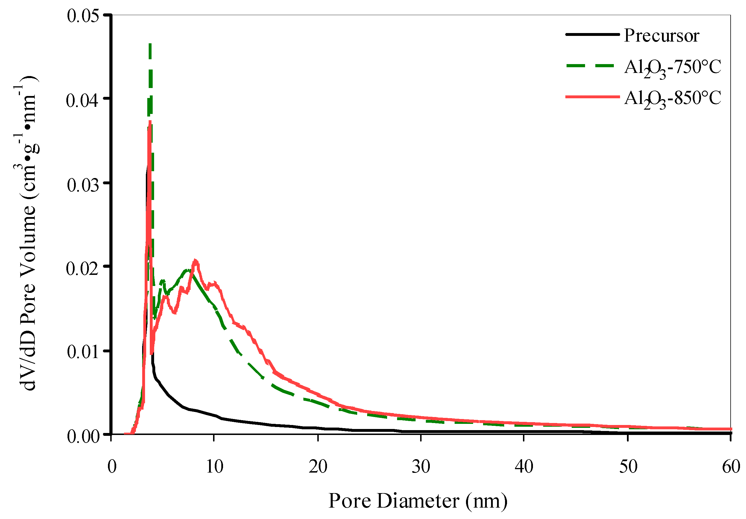
Figure iv. IR spectra of initial alumina support and a back up containing 4.5 wt % SiOtwo.
Figure 4. IR spectra of initial alumina back up and a support containing 4.five wt % SiO2.
Effigy 5. 29Si Magic Bending Spinning Nuclear Magnetic Resonance (MAS NMR) spectra of SiO2-modified supports.
Figure 5. 29Si Magic Angle Spinning Nuclear Magnetic Resonance (MAS NMR) spectra of SiO2-modified supports.
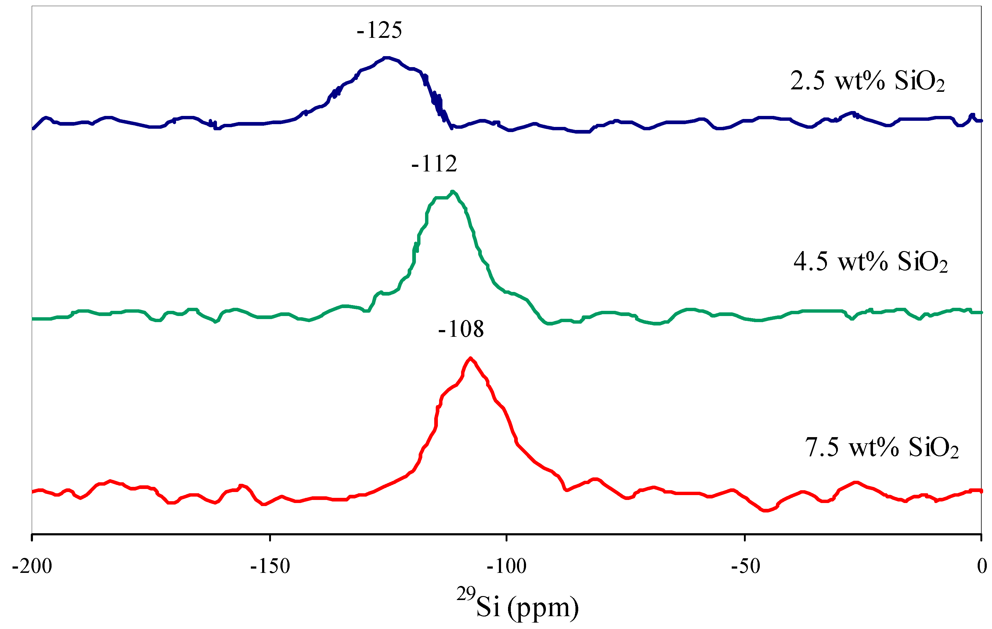
Figure 6. Pore size distribution for initial and SiO2-modified supports.
Figure 6. Pore size distribution for initial and SiO2-modified supports.

Figure 7. NHiii-TPD (temperature programmed desorption) patterns of initial and SiOtwo-modified supports.
Figure 7. NHthree-TPD (temperature programmed desorption) patterns of initial and SiO2-modified supports.
Effigy 8. X-ray diffraction patterns of catalysts.
Figure 8. X-ray diffraction patterns of catalysts.
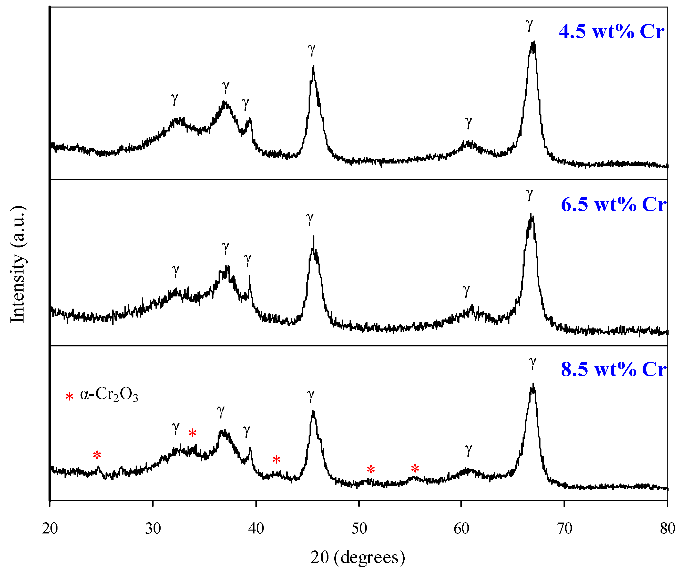
Figure 9. Pore size distribution for support with 4.five wt % SiO2 and for catalyst based on it.
Effigy 9. Pore size distribution for support with four.v wt % SiO2 and for catalyst based on it.
Effigy 10. Lengthened reflectance UV-Vis-spectra of catalysts (6.five wt % Cr; 0.viii wt % M).
Figure 10. Lengthened reflectance UV-Vis-spectra of catalysts (6.5 wt % Cr; 0.8 wt % K).
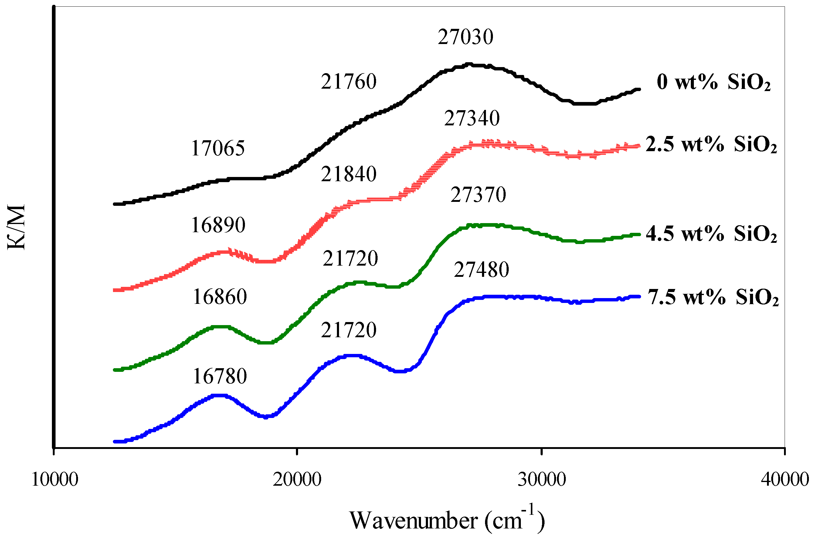
Figure 11. Raman-spectra of catalysts.
Figure 11. Raman-spectra of catalysts.
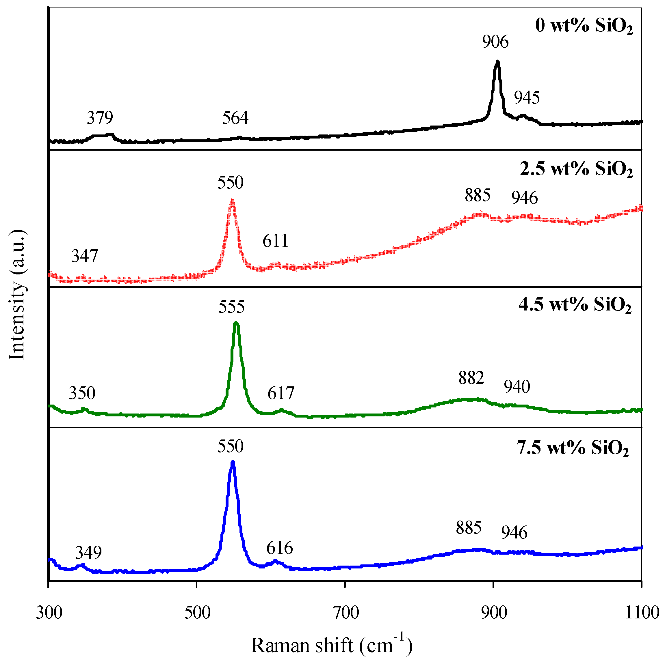
Figure 12. H2-temperature programmed reduction (TPR) profiles of catalysts.
Effigy 12. Htwo-temperature programmed reduction (TPR) profiles of catalysts.
Scheme two. Reaction between chromate ion and surface hydroxyl groups.
Scheme 2. Reaction between chromate ion and surface hydroxyl groups.
Scheme iii. Electrostatic interaction between chromate ion and positive-charged surface sites of alumina.
Scheme iii. Electrostatic interaction between chromate ion and positive-charged surface sites of alumina.
Scheme 4. Hydration of alumina and silica surface, their interaction with chromate ions.
Scheme 4. Hydration of alumina and silica surface, their interaction with chromate ions.
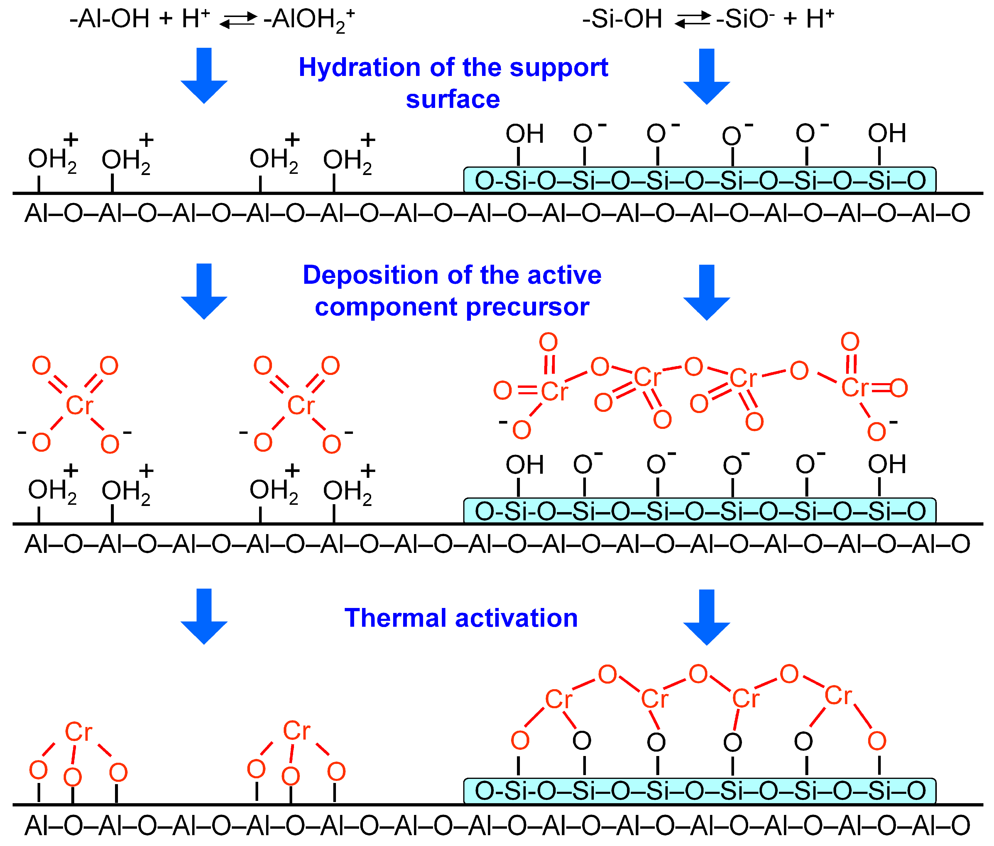
Figure xiii. Electron paramagnetic resonance (EPR) spectra of catalysts.
Effigy 13. Electron paramagnetic resonance (EPR) spectra of catalysts.
Effigy 14. Dehydrogenation rate (a) and cracking rate (b) versus fourth dimension on stream.
Figure 14. Dehydrogenation rate (a) and dandy rate (b) versus time on stream.

Table 1. Integral parameters of the porous system and the acidity of alumina supports.
| Sample | Temperature of Treatment | Crystalline Phase | Brunauer-Emmett-Teller (BET) Area (m2·g−1) | Pore Volume (cm3·g−one) | Total Number of Acid Sites (μmol·g−i) | Number of Acid Sites with Due east des.NHthree >150 kJ·mol−1 (μmol·g−1) |
|---|---|---|---|---|---|---|
| Precursor of Alumina | - | γ-AlOOH | 27 | 0.07 | - | - |
| Alumina support | 750 | γ-Al2O3 | 92 | 0.27 | 125.eight | xvi.ii |
| 800 | 83 | 0.26 | 102.iii | 10.0 | ||
| 850 | 62 | 0.26 | 91.8 | 8.v |
Tabular array 2. Porous system parameters of supports.
| SiOtwo Content (wt %) | BET Surface Area (mtwo·one thousand−1) | Pore Volume (cm3·g−i) | Distribution of Pore Volume (cm3·g−i) over Pore Diameters | ||
|---|---|---|---|---|---|
| <x nm | 10–xxx nm | >thirty nm | |||
| 0 | 83 | 0.26 | 0.08 | 0.13 | 0.05 |
| 2.five | 80 | 0.27 | 0.06 | 0.fifteen | 0.06 |
| iv.5 | 82 | 0.27 | 0.06 | 0.xv | 0.06 |
| 7.5 | 87 | 0.28 | 0.06 | 0.sixteen | 0.06 |
Table 3. Results from NH3-TPD (temperature programmed desorption) measurement of supports.
| SiO2 Content (wt %) | Total Number of Acid Sites (μmol·chiliad−i) | Distribution of Acid Sites (μmol·g−1) on the Energy of Ammonia Desorption | ||
|---|---|---|---|---|
| <100 kJ·mol−i | 100–150 kJ·mol−1 | >150 kJ·mol−1 | ||
| 0 | 102.3 | 25.6 | 66.seven | 10.0 |
| two.5 | 115.2 | 29.0 | 81.eight | four.five |
| four.five | 119.iv | 37.5 | 78.seven | iii.1 |
| seven.5 | 125.3 | 45.0 | 78.0 | ii.4 |
Table four. The composition of catalysts and their functioning in isobutane dehydrogenation.
| Chromium Content (wt %) | Potassium Content (wt %) | Surface Concentration of Chromium (atoms·nm−2) | Dehydrogenation Rate (μmolC4H10 ·yardcat −i·southward−1) | Cracking Rate (μmol[C1–C3]·gcat −1·south−one) Initial | |
|---|---|---|---|---|---|
| Initial | Afterwards Treatment at thousand °C | ||||
| 4.5 | 0.6 | half-dozen.5 | 2.seven | 2.4 | 0.32 |
| 6.five | 0 | x.0 | ii.8 | - | 0.47 |
| half-dozen.5 | 0.8 | 10.0 | 3.0 | three.1 | 0.29 |
| 8.five | i.i | xiii.5 | 3.1 | 2.5 | 0.27 |
Tabular array v. Limerick, Cr(VI) content, specific surface area and pore volume of the initial and SiO2-modified catalysts.
| Chromium Content (wt %) | Potassium Content (wt %) | SiOtwo Content (wt %) | Cr(Vi) Content i (wt %) | BET Area (gii·thou−ane) | Pore Volume (cmthree·g−1) |
|---|---|---|---|---|---|
| half-dozen.five | 0.8 | 0 | ii.v | 77 | 0.22 |
| 6.5 | 0.8 | 2.5 | ane.9 | 73 | 0.22 |
| 6.5 | 0.8 | 4.v | 1.6 | 74 | 0.22 |
| 6.5 | 0.eight | 7.v | 1.four | seventy | 0.22 |
Tabular array 6. Results from NH3-TPD measurement of catalysts.
| SiO2 Content (wt %) | Full Number of Acid Sites (μmol·chiliad−1) | Distribution of Acid Sites (μmol·thousand−ane) on the Energy of Ammonia Desorption | ||
|---|---|---|---|---|
| <100 kJ·mol−i | 100–150 kJ·mol−1 | >150 kJ·mol−1 | ||
| 0 | 72.iv | 9.3 | 53.four | 9.seven |
| 2.5 | 93.seven | 12.9 | 78.0 | 2.8 |
| 4.v | 102.8 | xv.seven | 85.v | 1.half-dozen |
| vii.5 | 109.six | 13.8 | 95.six | 0.two |
© 2016 by the authors; licensee MDPI, Basel, Switzerland. This commodity is an open admission article distributed nether the terms and atmospheric condition of the Creative Eatables Attribution (CC-By) license (http://creativecommons.org/licenses/past/4.0/).
richardsonansts1975.blogspot.com
Source: https://www.mdpi.com/2073-4344/6/10/162/htm
0 Response to "Light Alkane Dehydrogenation to Light Olefin Technologies a Comprehensive Review"
Enregistrer un commentaire